1. Overview
In this tutorial, we will walk you through creating a new model for a device to be supported on NMIS 8 and to add new metric.
What you’ll learn
- To obtain useful data to be used on the model.
- How to implement a new Model for a Net-SNMP device.
- Add a new metric.
- add a new graph.
What you’ll need
Our Opmantek Virtual Appliance (VM) from Opmantek.com
2. Set up your environment
If you haven’t done it yet. Download our latest Virtual Appliance from Opmantek.com
Import it into your favourite hypervisor, run the VM and get the IP address assigned to it.
For this tutorial, my NMIS8 environment is using 192.168.1.100, this IP address may be different on your set up.
You need to access the VM via SSH to edit the configuration files, the default credentials for the VM are:
username: root
password: NM1$88
3. Gathering data for the new model and model detection
We will need to have all the necessary standard (IETF/IEEE) MIBs and the vendor specific MIBs for the device to be modelled, once we have the MIBs the best way to interpret the MIBs is to complete an SNMP WALK of the device, first verify that you can use SNMP to access the device see the following article: Testing SNMP Connectivity from the NMIS Server with snmpwalk.
This time we will be using the Opmantek VM to monitor the devices but also, for simplicity, it will be used in this tutorial as the device to be modelled, so it will be having 2 roles, by default the NMIS Server is monitored itself and can be found as the localhost device.
First, we need to perform a snmpwalk against the device to obtain all the data and metric of the device. We need the "community" or password to access this information successfully, for the Opmantek VM, the community is: nmisGig8 and the ip address for this example is 192.168.1.100
The command must be run as follow:
snmpwalk -v 2c -c nmisGig8 192.168.1.100 .1
Expected output:
SNMPv2-MIB::sysDescr.0 = STRING: Linux Lab_Master 4.9.0-11-amd64 #1 SMP Debian 4.9.189-3+deb9u2 (2019-11-11) x86_64
SNMPv2-MIB::sysObjectID.0 = OID: NET-SNMP-MIB::netSnmpAgentOIDs.10
DISMAN-EVENT-MIB::sysUpTimeInstance = Timeticks: (166698) 0:27:46.98
SNMPv2-MIB::sysContact.0 = STRING: Root <root@nmis8> (configure /etc/snmp/snmpd.conf)
SNMPv2-MIB::sysName.0 = STRING: Lab_Master
SNMPv2-MIB::sysLocation.0 = STRING: Unknown (edit /etc/snmp/snmpd.conf)
SNMPv2-MIB::sysORLastChange.0 = Timeticks: (7) 0:00:00.07
SNMPv2-MIB::sysORID.1 = OID: SNMP-MPD-MIB::snmpMPDCompliance
SNMPv2-MIB::sysORID.2 = OID: SNMP-USER-BASED-SM-MIB::usmMIBCompliance
SNMPv2-MIB::sysORID.3 = OID: SNMP-FRAMEWORK-MIB::snmpFrameworkMIBCompliance
SNMPv2-MIB::sysORID.4 = OID: SNMPv2-MIB::snmpMIB
SNMPv2-MIB::sysORID.5 = OID: SNMP-VIEW-BASED-ACM-MIB::vacmBasicGroup
SNMPv2-MIB::sysORID.6 = OID: TCP-MIB::tcpMIB
SNMPv2-MIB::sysORID.7 = OID: IP-MIB::ip
SNMPv2-MIB::sysORID.8 = OID: UDP-MIB::udpMIB
SNMPv2-MIB::sysORID.9 = OID: SNMP-NOTIFICATION-MIB::snmpNotifyFullCompliance
SNMPv2-MIB::sysORID.10 = OID: NOTIFICATION-LOG-MIB::notificationLogMIB
SNMPv2-MIB::sysORDescr.1 = STRING: The MIB for Message Processing and Dispatching.
SNMPv2-MIB::sysORDescr.2 = STRING: The management information definitions for the SNMP User-based Security Model.
SNMPv2-MIB::sysORDescr.3 = STRING: The SNMP Management Architecture MIB.
SNMPv2-MIB::sysORDescr.4 = STRING: The MIB module for SNMPv2 entities
SNMPv2-MIB::sysORDescr.5 = STRING: View-based Access Control Model for SNMP.
SNMPv2-MIB::sysORDescr.6 = STRING: The MIB module for managing TCP implementations
SNMPv2-MIB::sysORDescr.7 = STRING: The MIB module for managing IP and ICMP implementations
SNMPv2-MIB::sysORDescr.8 = STRING: The MIB module for managing UDP implementations
SNMPv2-MIB::sysORDescr.9 = STRING: The MIB modules for managing SNMP Notification, plus filtering.
SNMPv2-MIB::sysORDescr.10 = STRING: The MIB module for logging SNMP Notifications.
SNMPv2-MIB::sysORUpTime.1 = Timeticks: (7) 0:00:00.07
SNMPv2-MIB::sysORUpTime.2 = Timeticks: (7) 0:00:00.07
SNMPv2-MIB::sysORUpTime.3 = Timeticks: (7) 0:00:00.07
SNMPv2-MIB::sysORUpTime.4 = Timeticks: (7) 0:00:00.07
SNMPv2-MIB::sysORUpTime.5 = Timeticks: (7) 0:00:00.07
SNMPv2-MIB::sysORUpTime.6 = Timeticks: (7) 0:00:00.07
SNMPv2-MIB::sysORUpTime.7 = Timeticks: (7) 0:00:00.07
SNMPv2-MIB::sysORUpTime.8 = Timeticks: (7) 0:00:00.07
SNMPv2-MIB::sysORUpTime.9 = Timeticks: (7) 0:00:00.07
SNMPv2-MIB::sysORUpTime.10 = Timeticks: (7) 0:00:00.07
IF-MIB::ifNumber.0 = INTEGER: 2
IF-MIB::ifIndex.1 = INTEGER: 1
IF-MIB::ifIndex.2 = INTEGER: 2
IF-MIB::ifDescr.1 = STRING: lo
IF-MIB::ifDescr.2 = STRING: Intel Corporation 82545EM Gigabit Ethernet Controller (Copper)
IF-MIB::ifType.1 = INTEGER: softwareLoopback(24)
IF-MIB::ifType.2 = INTEGER: ethernetCsmacd(6)
IF-MIB::ifMtu.1 = INTEGER: 65536
IF-MIB::ifMtu.2 = INTEGER: 1500
IF-MIB::ifSpeed.1 = Gauge32: 10000000
IF-MIB::ifSpeed.2 = Gauge32: 1000000000
IF-MIB::ifPhysAddress.1 = STRING:
IF-MIB::ifPhysAddress.2 = STRING: 8:0:27:c4:1f:3f
IF-MIB::ifAdminStatus.1 = INTEGER: up(1)
IF-MIB::ifAdminStatus.2 = INTEGER: up(1)
IF-MIB::ifOperStatus.1 = INTEGER: up(1)
IF-MIB::ifOperStatus.2 = INTEGER: up(1)
IF-MIB::ifLastChange.1 = Timeticks: (0) 0:00:00.00
IF-MIB::ifLastChange.2 = Timeticks: (3927) 0:00:39.27
IF-MIB::ifInOctets.1 = Counter32: 8315005
IF-MIB::ifInOctets.2 = Counter32: 1309639
IF-MIB::ifInUcastPkts.1 = Counter32: 41439
IF-MIB::ifInUcastPkts.2 = Counter32: 15249
IF-MIB::ifInNUcastPkts.1 = Counter32: 0
IF-MIB::ifInNUcastPkts.2 = Counter32: 38
IF-MIB::ifInDiscards.1 = Counter32: 0
--snip--
For a faster processing, you could use the command "snmpbulkwalk" instead, as it it optimised for high throughput.
Now that we know how to obtain useful information from the device, let’s add a new device model to NMIS.
Let’s imagine that we just got a brand new Debian 9 Server (our VM) and we need to create a model for it. At first, we are interested in the SysDescr and SysObjectId.
SNMPv2-MIB::sysDescr.0 = STRING: Linux Lab_Master 4.9.0-11-amd64 #1 SMP Debian 4.9.189-3+deb9u2 (2019-11-11) x86_64
SNMPv2-MIB::sysObjectID.0 = OID: NET-SNMP-MIB::netSnmpAgentOIDs.10
We need to obtain the vendor OID from the sysObjectID: NET-SNMP-MIB, it can be found using google. In a simple search we get that the OID is: 1.3.6.1.4.1.8072 (https://oidref.com/1.3.6.1.4.1.8072). The node code is: 8072.
The sysDescr: Debian 4.9.189-3+deb9u2 is telling us that this device is a Debian 9 with Kernel 4.9.189
Based on this information, we will creating a the model.
First we have to add the Node Code to the Enterprise.nmis, in this case the vendor is already present..
  '8071' => {
    'Enterprise' => 'Sandstorm Enterprises, Inc.',
    'OID' => '8071'
  },
  '8072' => {
    'Enterprise' => 'net-snmp',
    'OID' => '8072'
  },
  '8073' => {
    'Enterprise' => 'Lumos Technologies Inc',
    'OID' => '8073'
  },
Next, we update or add the information related to the device on /usr/local/nmis8/models/Model.nmis. We use the sysDescr to match a text pattern with a model.
The "net-snmp" section on the file currently looks like this:
    'Frogfoot Networks' => {
      'order' => {
        '10' => {
          'Ubiquiti' => 'Linux 2.6.3.'
        },
        '20' => {
          'FrogFoot' => 'Linux'
        }
      }
    },
    'net-snmp' => {
      'order' => {
        '5' => {
          'Checkpoint' => '2.6.18-92cp|2.6.18-92cpx86_64|2.4.21-21cpsmp'
        },
        '10' => {
          'net-snmp' => 'SunOS|Darwin|HP-UX'
        },
        '20' => {
          'net-snmp' => '.'
        }
      }
    },
    'Prime Computer' => {
      'order' => {
        '10' => {
          'net-snmp' => 'Cisco Secure Access Control System'
        }
      }
    },
We will add a new item to match a device that uses the net-snmp agent and has a sysDescr that includes the word "Debian". We could be more specific and add the version if it is required, however this is not the case.
It should look like this now:
    'Frogfoot Networks' => {
      'order' => {
        '10' => {
          'Ubiquiti' => 'Linux 2.6.3.'
        },
        '20' => {
          'FrogFoot' => 'Linux'
        }
      }
    },
    'net-snmp' => {
      'order' => {
        '5' => {
          'Checkpoint' => '2.6.18-92cp|2.6.18-92cpx86_64|2.4.21-21cpsmp'
        },
        '10' => {
          'net-snmp' => 'SunOS|Darwin|HP-UX'
        },
        '15' => {
          'Debian' => 'Debian'
        },
        '20' => {
          'net-snmp' => '.'
        }
      }
    },
    'Prime Computer' => {
      'order' => {
        '10' => {
          'net-snmp' => 'Cisco Secure Access Control System'
        }
      }
    },
With these changes, our model will be loaded for the device.
Now we test If our model have been added correctly and if it is detected automatically by NMIS.
In NMIS GUI, we add the new device. Use the SNMP Community, IP and a name for the device. Please note that the Model is selected as "Automatic" by default, an we will leave it as it is.
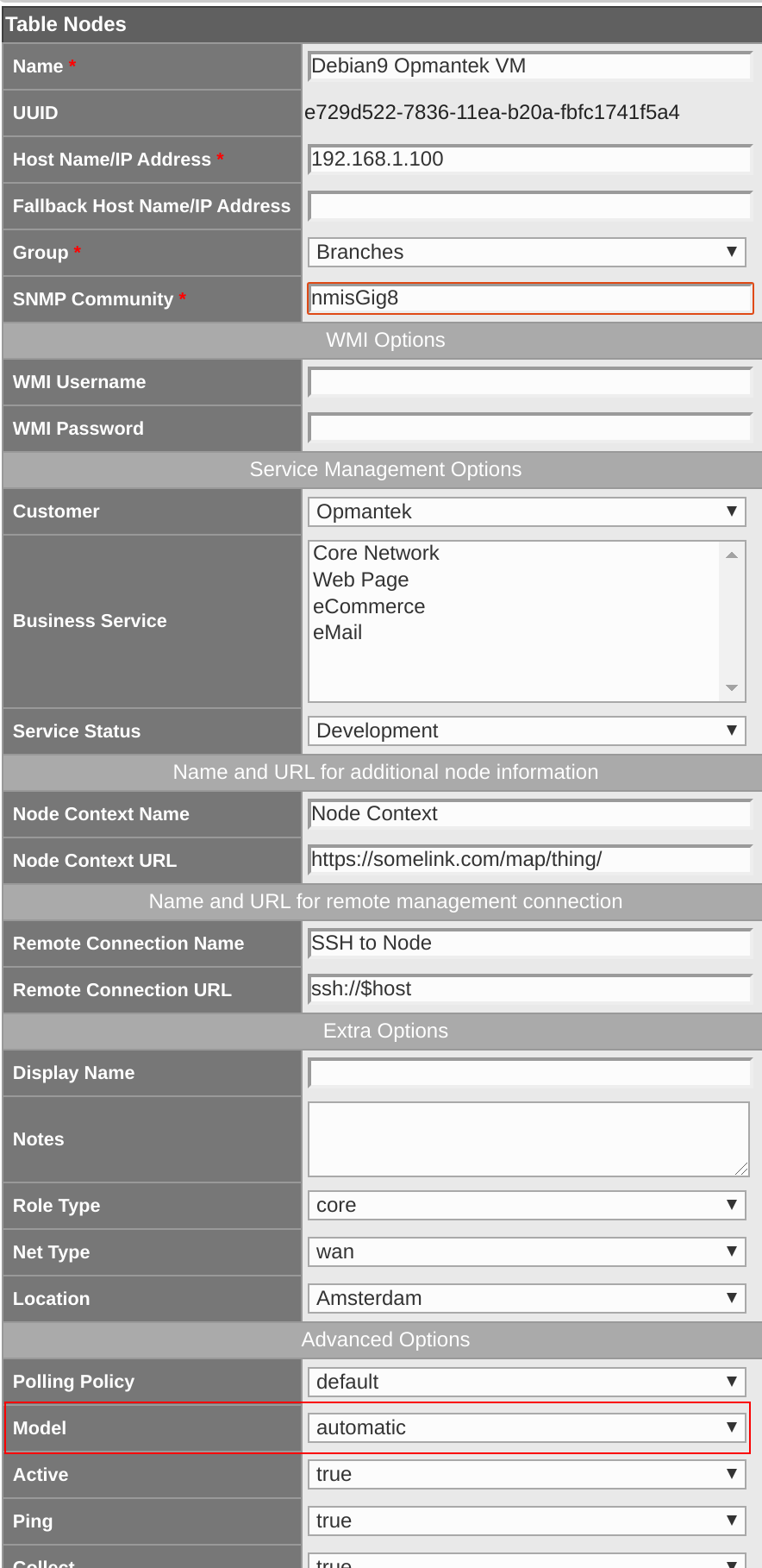
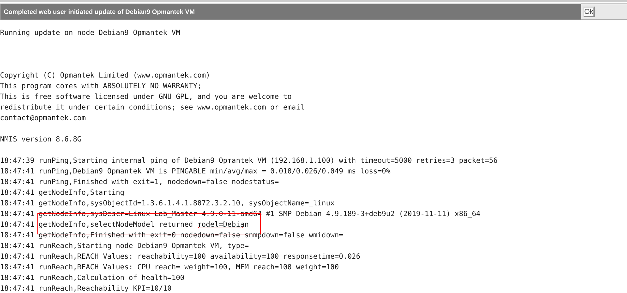
We "Add and Update" the new node. Now we can check the details returned of the process.
Here we can see that our model have been detected successfully.
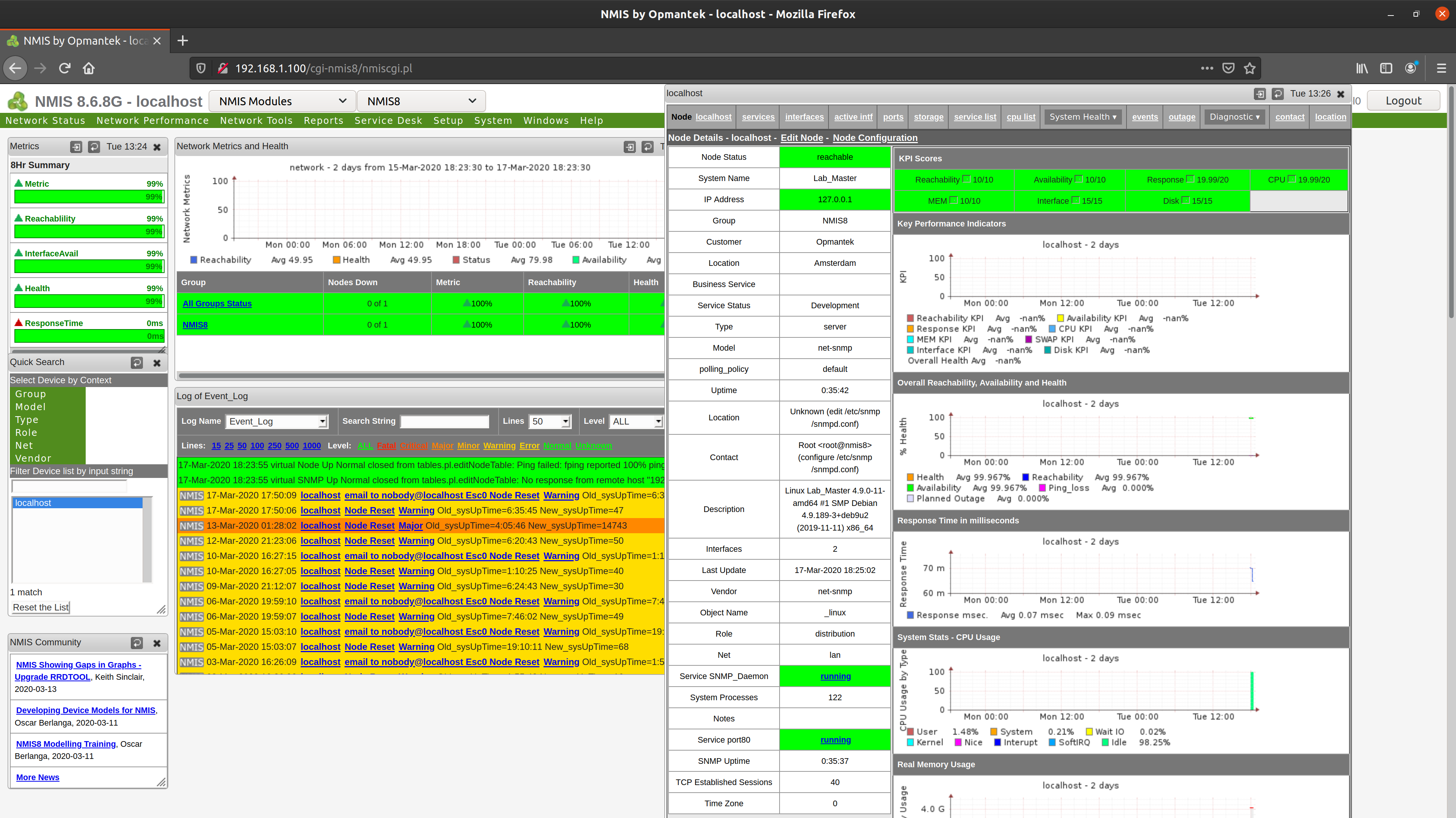
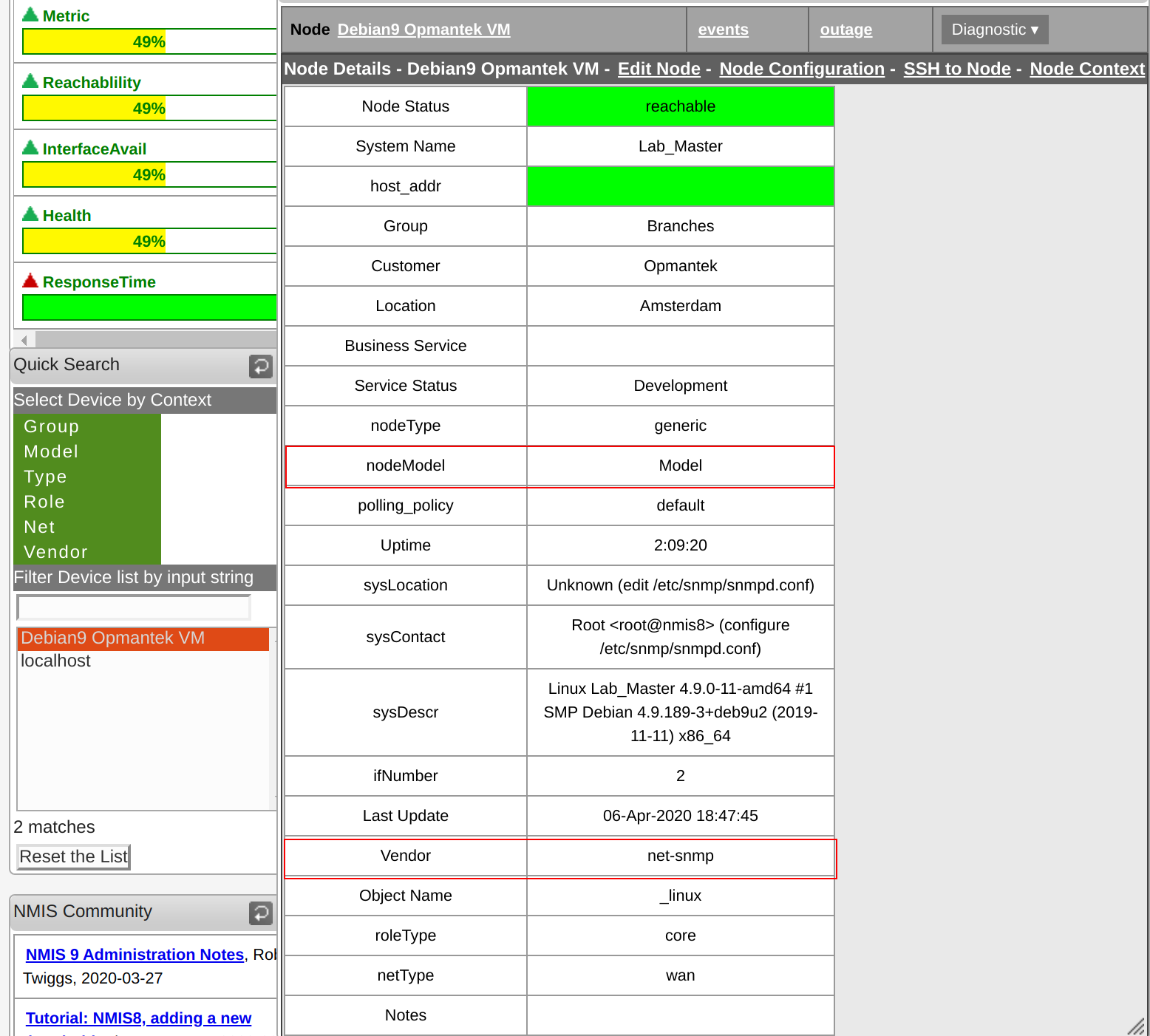
We get back to NMIS to review the recently created node. As you have noticed. Our new node doesn't use our model "Debian", instead we see that the "nodeModel" in use is "Model".
Don't worry, this is the expected behaviour, as we have only added the model to be detected by NMIS but not the modelling file to use, so NMIS uses the fallback model. Now it is time to create the Model File.
4. Model implementation
Model preparation
As you may have notice already, there are many devices that uses the same agents, in this example Linux Servers uses NET-SNMP, but Net-SNMP is available for many Unix and Unix-like operating systems and also for Microsoft Windows.
Tip: Many devices now uses NET-SNMP as Agent, most of the time, it’s a good idea to copy an existing model and tailor it to our needs instead of creating a new one.
This time lets copy the current /usr/local/nmis8/models/Model-net-snmp.nmis file and call it Model-Debian.nmis to adjusted to our needs. It is important to keep the naming convention here, as this is the way that NMIS will find the model.
Now, we will be working with an almost empty model and then add few sections, for this purpose we have to edit our /usr/local/nmis8/models/Model-Debian.nmis file, and remove everything on it, except the '-common-' section. Here the sample.
%hash = (
  '-common-' => {
    'class' => {
      'database' => {
        'common-model' => 'database'
      },
      'event' => {
        'common-model' => 'event'
      },
      'heading' => {
        'common-model' => 'heading'
      },
      'software' => {
        'common-model' => 'software'
      },
      'stats' => {
        'common-model' => 'stats'
      },
      'summary' => {
        'common-model' => 'summary'
      },
      'threshold' => {
        'common-model' => 'threshold'
      }
    }
  }
);
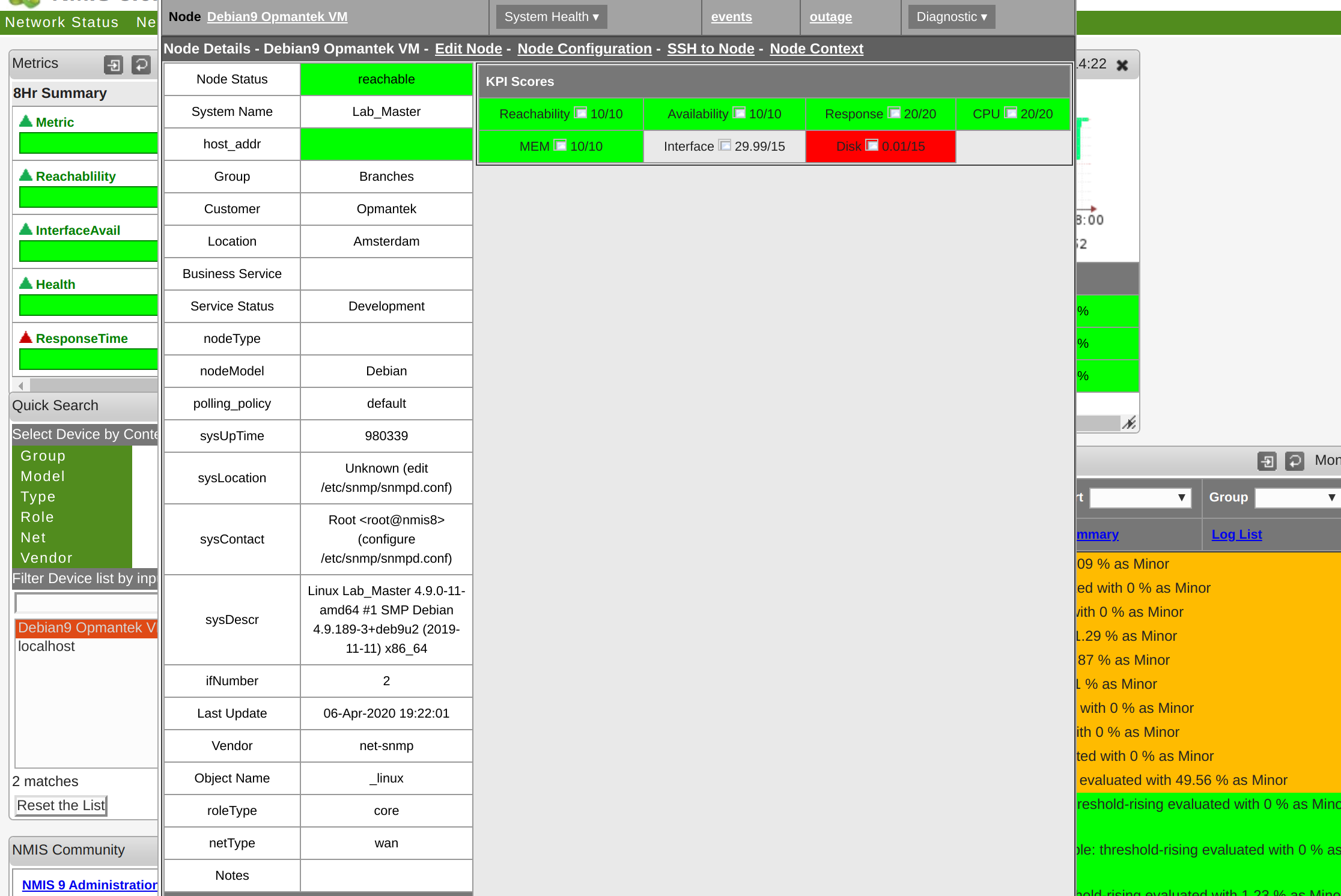
Let's see the result of using this model. We need to run an Update on the device and then refresh our Node View. For the manual update, ssh into the VM and run:
/usr/local/nmis8/bin/nmis.pl type=update node="Debian9 Opmantek VM" debug=1
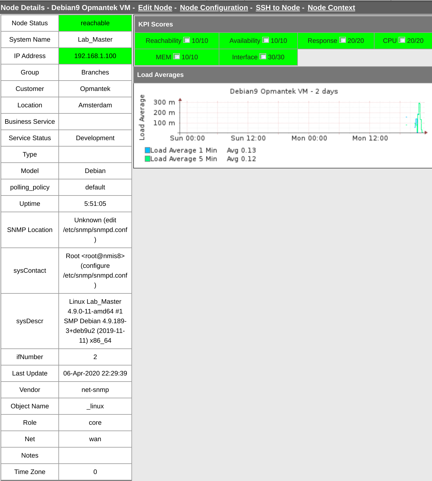
And the refreshed view should look like this:
Model construction
We have the need to add new metrics to our model. In this case we are interested to add "the Linux system load". its table is represented with the oid: 1.3.6.1.4.1.2021.10.1 (https://oidref.com/1.3.6.1.4.1.2021.10.1)
Let's see what data we get using snmpwalk on that OID.
❯ snmpwalk -v 2c -c nmisGig8 192.168.1.100 1.3.6.1.4.1.2021.10.1

UCD-SNMP-MIB::laIndex.1 = INTEGER: 1
UCD-SNMP-MIB::laIndex.2 = INTEGER: 2
UCD-SNMP-MIB::laIndex.3 = INTEGER: 3
UCD-SNMP-MIB::laNames.1 = STRING: Load-1
UCD-SNMP-MIB::laNames.2 = STRING: Load-5
UCD-SNMP-MIB::laNames.3 = STRING: Load-15
UCD-SNMP-MIB::laLoad.1 = STRING: 0.02
UCD-SNMP-MIB::laLoad.2 = STRING: 0.04
UCD-SNMP-MIB::laLoad.3 = STRING: 0.04
UCD-SNMP-MIB::laConfig.1 = STRING: 12.00
UCD-SNMP-MIB::laConfig.2 = STRING: 12.00
UCD-SNMP-MIB::laConfig.3 = STRING: 12.00
UCD-SNMP-MIB::laLoadInt.1 = INTEGER: 2
UCD-SNMP-MIB::laLoadInt.2 = INTEGER: 4
UCD-SNMP-MIB::laLoadInt.3 = INTEGER: 4
UCD-SNMP-MIB::laLoadFloat.1 = Opaque: Float: 0.020000
UCD-SNMP-MIB::laLoadFloat.2 = Opaque: Float: 0.040000
UCD-SNMP-MIB::laLoadFloat.3 = Opaque: Float: 0.040000
UCD-SNMP-MIB::laErrorFlag.1 = INTEGER: noError(0)
UCD-SNMP-MIB::laErrorFlag.2 = INTEGER: noError(0)
UCD-SNMP-MIB::laErrorFlag.3 = INTEGER: noError(0)
UCD-SNMP-MIB::laErrMessage.1 = STRING:
UCD-SNMP-MIB::laErrMessage.2 = STRING:
UCD-SNMP-MIB::laErrMessage.3 = STRING:
Great, we are interested on the "laLoad" values, laLoad.1 (1.3.6.1.4.1.2021.10.1.3.1) and laLoad.2 (1.3.6.1.4.1.2021.10.1.3.2) to be more exact. In other words, we want to work with "1 Minute Load" and "5 Minutes Load" for now.
With this details we can start building up our model, First we have to add new section sibling of the -common- section and name it "system". Inside the system section we will be creating 2 more section, the "rrd" and "sys" sections. It should look like this:
%hash = (
  '-common-' => {
    'class' => {
      'database' => {
        'common-model' => 'database'
      },
      'event' => {
        'common-model' => 'event'
      },
      'heading' => {
        'common-model' => 'heading'
      },
      'software' => {
        'common-model' => 'software'
      },
      'stats' => {
        'common-model' => 'stats'
      },
      'summary' => {
        'common-model' => 'summary'
      },
      'threshold' => {
        'common-model' => 'threshold'
      }
    }
  },
  'system' => {
    'rrd' => {

      },
    },
    'sys' => {

      },
    }
  },
);
Now, inside the rrd and sys sections, we will be adding the "laload" item section, the name on this section is important as it will hold a relation between the model and the database where the data is stored. Inside this "laload" item section we will add and "snmp" section.
--snip--
  'system' => {
    'rrd' => {
      'laload' => {
        'snmp' => {

        }
      },
    },
    'sys' => {
      'laLoad' => {
        'snmp' => {

        }
      },
    }
  },
--snip--
Now we add the items section that we want to model, as we decided before, it will be laLoad1 and laLoad2. Once again the name of the items are important as it will represent the Data Source or DS on our database (RRD file). We need to add the element "oid" for each item. The oid must could be the numeric snmp OID or a previously mapped OID (we will see option later). In this case we will use the numeric OID.
--snip--
  'system' => {
    'rrd' => {
      'laload' => {
        'snmp' => {
          'laLoad1' => {
            'oid' => '1.3.6.1.4.1.2021.10.1.3.1',
          },
          'laLoad5' => {
            'oid' => '1.3.6.1.4.1.2021.10.1.3.2',
          }
        }
      },
    },
    'sys' => {
      'laLoad' => {
        'snmp' => {
          'laLoad1' => {
            'oid' => '1.3.6.1.4.1.2021.10.1.3.1'
          },
          'laLoad5' => {
            'oid' => '1.3.6.1.4.1.2021.10.1.3.2'
          }
        }
      },
    }
  },
--snip--
For the rrd section we need to specify the type of data and range that it will be saving on the RRD file. For this we have to use the "option" element, it indicates if it is a counter or a gauge, and the lower and upper value limits, being “U” equivalent to Unlimited.
In this case it is a "gauge", and the values range start from 0, so we will be using: 'option' => 'gauge,0:U'.
--snip--
  'system' => {
    'rrd' => {
      'laload' => {
        'snmp' => {
          'laLoad1' => {
            'oid' => '1.3.6.1.4.1.2021.10.1.3.1',
            'option' => 'gauge,0:U'
          },
          'laLoad5' => {
            'oid' => '1.3.6.1.4.1.2021.10.1.3.2',
            'option' => 'gauge,0:U'
          }
        }
      },
    },
    'sys' => {
      'laLoad' => {
        'snmp' => {
          'laLoad1' => {
            'oid' => '1.3.6.1.4.1.2021.10.1.3.1'
          },
          'laLoad5' => {
            'oid' => '1.3.6.1.4.1.2021.10.1.3.2'
          }
        }
      },
    }
  },
--snip--
For now we will be adding the item 'no_graphs' => '1' to the rrd section. This item or option indicates that we are not going to use a graph with the data collected. We will change this option further in this tutorial, but so far this is what we need to start testing our implementation before moving on to the graphs.
--snip--
  'system' => {
    'rrd' => {
      'laload' => {
        'no_graphs' => '1',
        'snmp' => {
          'laLoad1' => {
            'oid' => '1.3.6.1.4.1.2021.10.1.3.1',
            'option' => 'gauge,0:U'
          },
          'laLoad5' => {
            'oid' => '1.3.6.1.4.1.2021.10.1.3.2',
            'option' => 'gauge,0:U'
          }
        }
      },
    },
    'sys' => {
      'laLoad' => {
        'snmp' => {
          'laLoad1' => {
            'oid' => '1.3.6.1.4.1.2021.10.1.3.1'
          },
          'laLoad5' => {
            'oid' => '1.3.6.1.4.1.2021.10.1.3.2'
          }
        }
      },
    }
  },
--snip--
Before testing our implementation, we must add the details of the database to use to store the data obtained. For this, we need to edit the /usr/local/nmis8/models/Common-database.nmis file and add the reference to it. The name must match exactly with the name used on the rrd section of the model. The right side must indicate where the rrd will be saved and its name.
--snip--
      'jnxOperations' => '/nodes/$node/health/jnxOperations-$index.rrd',
      'jnxSourceClassUsage' => '/nodes/$node/health/jnxSCUstats-$index.rrd',
    'laload' => '/nodes/$node/health/laload.rrd',
      'memUsageUtil' => '/nodes/$node/health/mem-$index.rrd',
      'memUtil' => '/nodes/$node/health/mem.rrd',
--snip--
Now we can test it, running an "Update" and a "Collect" using the debug and model options:
$ /usr/local/nmis8/bin/nmis.pl type=update node="Debian9 Opmantek VM" debug=1
$/usr/local/nmis8/bin/nmis.pl type=collect node="Debian9 Opmantek VM" debug=1 force=true model=true
At this stage we are interested on the output of the "Collect" . It may give us information related to the sections that we are modelling. As we can see here, we got the right information for laLoad1 and laLoad5 and the data was successfully saved into the RRD database.
21:45:29 getValues, wanted section=, now handling section=laLoad
21:45:29 getValues, class: index= port= suffix=
21:45:29 getValues, loaded 2 values, status: ok
MODEL loadInfo Debian9 Opmantek VM class=system:
  :  oid=1.3.6.1.4.1.2021.10.1.3.2 name=laLoad5 value=0.20
  :  oid=1.3.6.1.4.1.2021.10.1.3.1 name=laLoad1 value=0.30
21:45:29 updateNodeInfo, sysUpTime: Old=5:06:48 New=5:06:48
21:45:29 checkPIX, Starting
21:45:29 checkPIX, Finished
MODEL Debian9 Opmantek VM: nodedown=false sysUpTime=5:06:48 sysObjectID=1.3.6.1.4.1.8072.3.2.10
21:45:29 updateNodeInfo, Finished with exit=1
MODEL Debian9 Opmantek VM: role=core type= sysObjectID=1.3.6.1.4.1.8072.3.2.10 sysObjectName=_linux
MODEL Debian9 Opmantek VM: sysDescr=Linux Lab_Master 4.9.0-11-amd64 #1 SMP Debian 4.9.189-3+deb9u2 (2019-11-11) x86_64
MODEL Debian9 Opmantek VM: vendor=net-snmp model=Debian interfaces=2
21:45:29 getNodeData, Starting Node get data, node Debian9 Opmantek VM
21:45:29 getData, index= port= class=system section=
21:45:29 getValues, wanted section=, now handling section=laload
21:45:29 getValues, class: index= port= suffix=
21:45:29 getValues, loaded 2 values, status: ok
MODEL getData Debian9 Opmantek VM class=system:
  section=laload index= port=
    oid=1.3.6.1.4.1.2021.10.1.3.1 name=laLoad5 value=0.30
    oid=1.3.6.1.4.1.2021.10.1.3.1 name=laLoad1 value=0.30
21:45:29 updateRRD, Starting RRD Update Process, type=laload, index=, item=
21:45:29 getFileName, filename of type=laload is /usr/local/nmis8/database/nodes/debian9 opmantek vm/health/laload.rrd
21:45:29 updateRRD, database /usr/local/nmis8/database/nodes/debian9 opmantek vm/health/laload.rrd exists and is R/W
21:45:29 updateRRD, DS laLoad5:laLoad1, 2
21:45:29 updateRRD, value N:0.30:0.30, 16 bytes
21:45:29 getNodeData, Finished
Graph construction
So far we have the collected the data from the device and stored in our database, now we need to show that data in a useful though a graph.
We need to specify the graph on our model, we used the 'no_graphs' => '1' option to indicate that we didn't want a graph, now we have to replace this option with: 'graphtype' => 'laload', where "laload" is the name of the graph that we will be using, so the filename of our graph should be: /usr/local/nmis8/models/Graph-laload.nmis
--snip--
  'system' => {
    'rrd' => {
      'laload' => {
        'graphtype' => 'laload'
        'snmp' => {
          'laLoad1' => {
            'oid' => '1.3.6.1.4.1.2021.10.1.3.1',
            'option' => 'gauge,0:U'
          },
          'laLoad5' => {
            'oid' => '1.3.6.1.4.1.2021.10.1.3.2',
            'option' => 'gauge,0:U'
          }
        }
      },
    },
    'sys' => {
      'laLoad' => {
        'snmp' => {
          'laLoad1' => {
            'oid' => '1.3.6.1.4.1.2021.10.1.3.1'
          },
          'laLoad5' => {
            'oid' => '1.3.6.1.4.1.2021.10.1.3.2'
          }
        }
      },
    }
  },
--snip--
Now, let's create /usr/local/nmis8/models/Graph-laload.nmis. and add the following details:
%hash = (
	'title' => {

	},
	'vlabel' => {

	},
	'option' => {

	}
);
As we can see here, the graph need basic elements to be constructed. A tittle section, a vlabel (vertical label) and the options. For the title we must have a title for the standard version and for the short version. This is standard across all graphs and any other graph can be used as reference. The vlabel has a description of the graph and options are also divided in 2 sections: "standard" and "small", been this section where we define the graph itself.
%hash = (
	'title' => {
		'standard' => '$node - $length from $datestamp_start to $datestamp_end',
		'short' => '$node - $length'
	},
	'vlabel' => {
		'standard' => 'Load Average'
	},
	'option' => {
		'standard' => [],
		'small' => []
	}
);
Here we have the graph completed. I will explain the details below.
%hash = (
	'title' => {
		'standard' => '$node - $length from $datestamp_start to $datestamp_end',
		'short' => '$node - $length'
	},
	'vlabel' => {
		'standard' => 'Load Average'
	},
	'option' => {
		'standard' => [
			'DEF:laLoad1=$database:laLoad1:AVERAGE',
			'LINE1:laLoad1#00BFFF:Load Average 1 Min',
			'GPRINT:laLoad1:MIN:Minimum %1.2lf',
			'GPRINT:laLoad1:AVERAGE:Avg %1.2lf',
			'GPRINT:laLoad1:MAX:Max %1.2lf\\n',


			'DEF:laLoad5=$database:laLoad5:AVERAGE',
			'LINE1:laLoad5#00FF7F:Load Average 5 Min',
			'GPRINT:laLoad5:MIN:Minimum %1.2lf',
			'GPRINT:laLoad5:AVERAGE:Avg %1.2lf',
			'GPRINT:laLoad5:MAX:Max %1.2lf\\n',
		],
		'small' => [
			'DEF:laLoad1=$database:laLoad1:AVERAGE',
			'DEF:laLoad5=$database:laLoad5:AVERAGE',
			'LINE1:laLoad1#00BFFF:Load Average 1 Min',
			'GPRINT:laLoad1:AVERAGE:Avg %1.2lf\\n',
			'LINE1:laLoad5#00FF7F:Load Average 5 Min',
			'GPRINT:laLoad5:AVERAGE:Avg %1.2lf\\n',
		]
	}
);
Let’s examine the first line inside “option -> standard” to understand what is the meaning of each term.
DEF:laLoad1=$database:laLoad1:AVERAGE
DEF:<vname>=<rrdfile>:<ds-name>:<CF>
vname: Internal variable where the data from the RRD will be stored, in our case: “laLoad1”
rrdfile: The RRD where the data is stores, in our case: $database (already defined in Common-database.nmis)
ds-name: The Data Source name used to store particular data into the RRD, in our case “laLoad1”
CF: The Consolidation Function can be AVERAGE, MINIMUM, MAXIMUM, or LAST, in our case: “AVERAGE”
The ds-name(RouteNumber) must be exactly the same as name given to the variable assigned in the model (“system -> rrd -> nodehealth -> snmp”).
The next item defines the type of drawing that will be done with the data.
LINE1:laLoad1#00BFFF:Load Average 1 Min
LINE:value[#color]:[legend]
LINE1: Type of drawing, in our case: a Line.
Value: The value or variable holding the value, in our case: load value.
#color: Hexadecimal color value, in our case: #00BFFF.
Legend: The legend associated to the value.
The last two lines are similar, are the calculated values displayed as part of the legend.
Basically, the graph is defined based on the RRD Tool graph system and additional information and extended options can be found here: https://oss.oetiker.ch/rrdtool/doc/rrdgraph.en.html
Now that we have the graph constructed, we need to add it to the system section to be displayed as below:
--snip--
  'system' => {
    'nodegraph' => 'laload',
    'rrd' => {
      'laload' => {
        'graphtype' => 'laload'
        'snmp' => {
          'laLoad1' => {
            'oid' => '1.3.6.1.4.1.2021.10.1.3.1',
            'option' => 'gauge,0:U'
          },
          'laLoad5' => {
            'oid' => '1.3.6.1.4.1.2021.10.1.3.2',
            'option' => 'gauge,0:U'
          }
        }
      },
    },
    'sys' => {
      'laLoad' => {
        'snmp' => {
          'laLoad1' => {
            'oid' => '1.3.6.1.4.1.2021.10.1.3.1'
          },
          'laLoad5' => {
            'oid' => '1.3.6.1.4.1.2021.10.1.3.2'
          }
        }
      },
    }
  },
--snip--
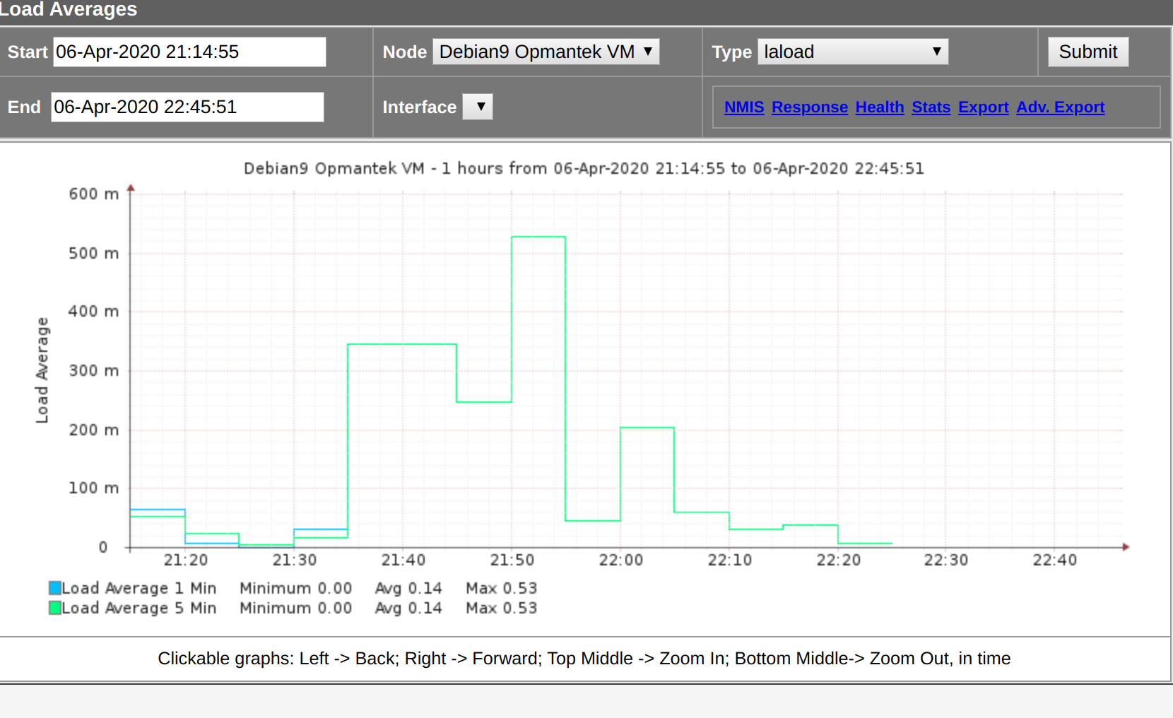
Once again, we perform an "Update" and a "Collect", then we refresh the node view on NMIS and we have our graph.