| Table of Contents |
|---|
Basic Modelling
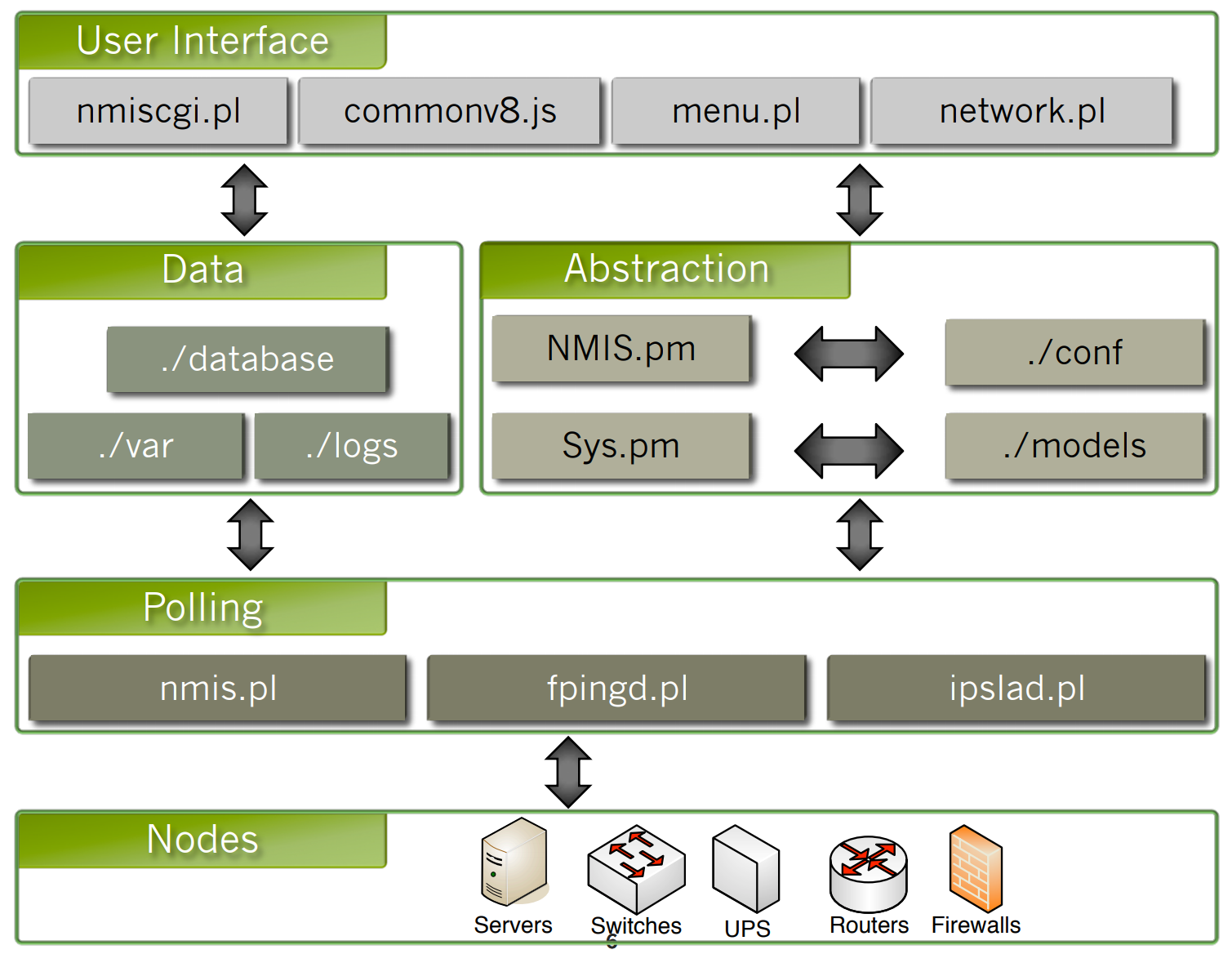
NMIS 8 Architecture
The nodes information is accessed using daemons or pollers that are part of the Polling System. The information obtained at this level could be ICMP (Internet Control Message Protocol), SNMP (Simple Network Management Protocol), etc.
...
At the User Interface level, most of the heavy lifting is done by Network.pl, which loads up the Abstraction System and Data to produce the views, dashboard and everything displayed to the user in a meaningful and useful manner.
Modelling process
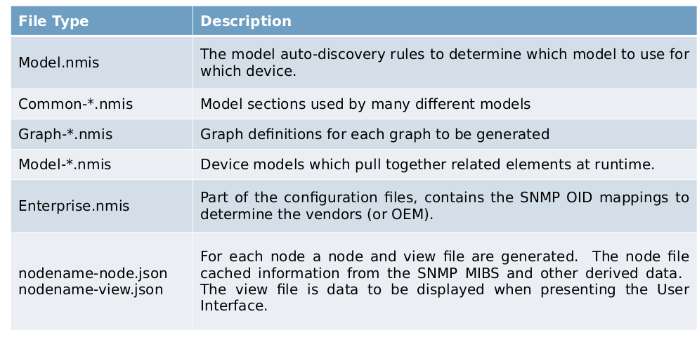
Types of Model Files
This are the files that we need to get familiar with in order to be able to successfully follow the modelling process.
...
nodename-node.json and nodename-node.json : For each node a node and view file are generated and maintained after a poll cycle (Update and Collect). It contains node cached information from the SNMP MIBS and other derived data, the data that it holds is temporarily persisted. The view file is data to be displayed when presenting the User Interface.
Overview
1. Collect From Device
The first step is to collect from the device sysDescr (System Description) and SysObjectId (Vendor's authoritative identification of the device). NMIS does a SNMP GET on the route and gets the sysDescr and SysObjectId.
...
| Code Block | ||
|---|---|---|
| ||
'sysDescr' => 'Hardware: Intel64 Family 6 Model 15 Stepping 6 AT/AT COMPATIBLE - Software: Windows Version 6.1 (Build 7600 Multiprocessor Free)' 'sysObjectID' => '1.3.6.1.4.1.311.1.1.3.1.1' |
2. Determine the Vendor
Compare the sysObjectID to the Enterprises defined in Enterprise.nmis, the OID 311 will return the value of Enterprise, in this particular case, is 'Microsoft'.
...
| Code Block | ||||
|---|---|---|---|---|
| ||||
'311' => {
 'OID' => '311',
 'Enterprise' => 'Microsoft'
}, |
3. Auto-discovery model
To obtain the model to load, a matching process needs to be done on the Model.nmis file. The vendor name obtained from the previous step is used to find the section that matches its value, once we have the section to use, a regular expression will be perform to match the value of every item on that section against the sysDescr, this process will be done in numerical ascending order.
In this example, the vendor name will match the “Microsoft” section on the Model.nmis file, then, it will look for a match in order, starting from 10, it will try to identify if the value 'Windows Version 5.2' is included in the sysDescr. It will keep looking until a match is found. In this case, 'Windows Version 6.1' is a match, so the model to load is set to: 'Windows2008'.
| Code Block | ||||
|---|---|---|---|---|
| ||||
'Microsoft' => {
  'order' => {
    '30' => {
      'Windows2000' => 'Windows 2000 Version 5.0'
    },
    '10' => {
      'Windows2003' => 'Windows Version 5.2'
    },
    '20' => {
      'Windows2008' => 'Windows Version 6.1'
    }
  }
}, |
4. Load the model
The model result from Model.nmis will be loaded, the model filename must start with “Model-” followed by the name of the model as specified on the Model.nmis with extension “.nmis”.In our example, the model to use is 'Windows2008', so the file must be called: Model-Windows2008.nmis
...
| Code Block | ||||
|---|---|---|---|---|
| ||||
'system' => {
  --snip--
},
'systemHealth' => {
  --snip--
},
'interface' => {
  --snip--
},
'device' => {
  --snip--
}, |
5. Load the data
Uses this model to collect device specific information from the device or to load the cached data from nmis8/var. If there is no file on the var directory for the device, NMIS will start collecting SNMP data from the device.
This process happens every time when dealing with the devices. When using the GUI, the model will be loaded with no SNMP enabled, however, when using NMIS.pl the model will be loaded with SNMP enabled.
Structure of a model
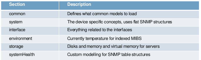
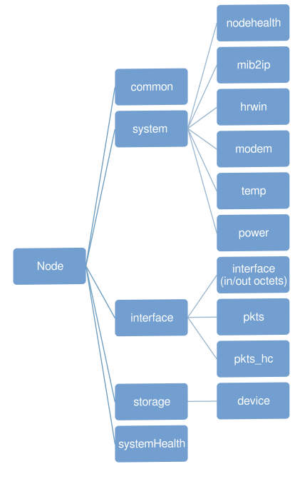
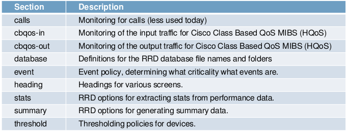
Common Models
Modelling a Device
Goal for Modelling
What is the goal for the modelling? Just standard type support, or more advanced collection, do you want to collect some performance data about how a protocol is operating, or verify the number of sessions a firewall is running.
Sometimes you can find the source MIB in the documentation or a whitepaper, but sometimes it is very difficult to determine where the needed data is stored. If possible ask a product expert who is familiar with that specific product.
Device Instrumentation
Many times, people want to graph CPU and Memory, but not all devices support the collection of this information, you can only ask NMIS to collect something which the device has the instrumentation for, the MIBs should tell you if it is possible.
Relevance of Instrumentation
For Cisco routers, it is very handy to monitor CPU load, it is an excellent metric for how the device is performing, however on some newer Cisco devices, the processing is distributed and performed in hardware, so the CPU load is still handy but it may not be providing the information you need.
Verify the MIB Operation
Now you know what you want to collect and monitor, verify that the MIB operates the way the documentation says it does and verify that it works the way you think it does.
What do we need
Device Access
You can model a device without having one, but it is REALLY HARD, having SNMP readonly access to a device is vital for success.
SNMP MIBS
You will need to have all the necessary standard (IETF/IEEE) MIBs and the vendor specific MIBs for the device to be modelled.
SNMPWALK (SNMP Dump)
Once you have the MIBs the best way to interpret the MIBs is to complete an SNMP WALK of the device, first verify that you can use SNMP to access the device.
...
| Code Block | ||
|---|---|---|
| ||
snmpwalk -m ALL -M ~/mibs -v 2c -c GOODCOMMUNITY > snmp_dump.txt |
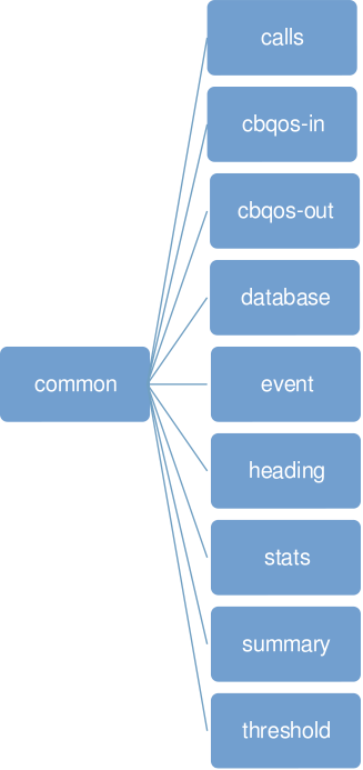
MIB Decoding Example
Let’s take this example, here snmpwalk couldn’t find a suitable MIB file to translate the SNMP data returned from the device. In this example, we are interested in the last three elements.
...
| Code Block | ||||
|---|---|---|---|---|
| ||||
system OBJECT IDENTIFIER ::= { powerMIB 2 }
systemVoltage OBJECT-TYPE
	SYNTAX Integer32
	MAX-ACCESS read-only
	STATUS current
	DESCRIPTION "
		System voltage, stored as mV, including positive or negative
		sign. The integer 2147483647 represents invalid value."
	::= { system 2 }

systemCurrent OBJECT-TYPE
	SYNTAX Integer32
	MAX-ACCESS read-only
	STATUS current
	DESCRIPTION "
		System current, stored as mA, including positive or negative
		sign. The integer 2147483647 represents invalid value."
	::= { system 3 }

systemUsedCapacity OBJECT-TYPE
	SYNTAX Integer32
	MAX-ACCESS read-only
	STATUS current
	DESCRIPTION "
		Used capacity, stored as % of the total capacity.
		The integer 2147483647 represents invalid value."
::= { system 4 } |
MIB tree for the three components
Here we have a graphical representation on how the MIB components are decomposed.
Implementing a new device model
As part of this training, we are going to implement our own model together, step by step, to have a better understanding on how the process is done. Now that we know how to decode a MIB and obtain the data we need to incorporate to the model using snmpwalk, let’s add a new device model to NMIS.
...
Now you should be able to do it yourself, please refer to the Hands-On guide included with this material*. (*The mentioned material has not been created yet)
Adding a New Metric to Node Health
So far, we have been able to create our new model, now it is time to incorporate new metrics. It is very common and useful to display metrics on the Node Health. Let’s say that we have a Cisco Router and it is capable to provide the number of routes seen by a router, to keep things simple, we are going to edit an existing model for Cisco devices. As we know, a MIB dump is needed; it can be obtained running SNMPWALK against the device, as we are only interested now about the number of routes, we are going to focus on these 2 elements:
...
Basically, the graph is defined based on the RRD Tool graph system and additional information and extended options can be found here: https://oss.oetiker.ch/rrdtool/doc/rrdgraph.en.html
System Section
We have added a new metric to the nodeHealth section, but sometimes we need to add new concepts to the device model and create their own RRD files.
...
This is how the standard version looks:
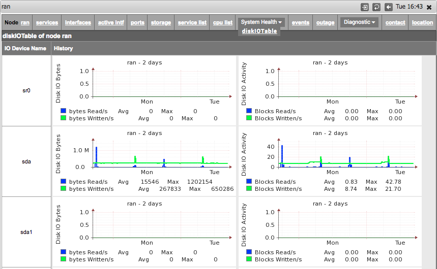
System Health Section (Indexes)
Often a section of data that is useful to have displayed in NMIS is presented in SNMP as a table. In order to model this NMIS modelling supports a "systemHealth" section that allows indexing to be used.
...
It is a standard SNMP Table construct. For every disk that we got, there is a index assigned to it and every disk will have “diskIOIndex,diskIODevice,diskIONRead,etc”.
Model file
The systemHealth section is a "top-level" section, which means it does not sit inside another section.
...
In this example "diskIOTable" is used.
sys section
In the above code snippet there is a 'sys' section, this is where data that will be stored in the Nodename-node.nmis file is defined. This is also where data that is needed for gathering the RRD section is defined. If you want to see the latest value gathered by NMIS for these MIBS check the Nodename-node.nmis file for your node. The values defined inside the snmp section are like any other part of the model.
...
ensures that the last three numbers are used for indexing.
rrd section
The rrd section defines what data will be collected and stored into rrd's. Once again, the values defined inside the snmp section are like any other part of the model.
...
'control' => 'CVAR=diskIODevice;$CVAR =~ /sda|sr|disk|xvda|dm\-/',
This tells NMIS that the OID diskIODevice should be checked and only capture the values into RRD if they match the regular expression given.indexed => 'true',
Tell NMIS this is an indexed table, it will then go and use the index specified in the sys section above to iterate.graphtype => 'diskio-rw,diskio-rwbytes'
what graph-types will this rrd section create data for.snmp => 'diskio-rw,diskio-rwbytes'
what graph-types will this rrd section create data for.
4.aoidcan be something nmis_mibs.oid or an OID.
4.boptionis the data a counter or gauge, and what are the lower and upper limits.
e.g:'option' => 'counter,0:U'
4.ctitlewhat to call it when it displayed.
Common-heading.nmis file
These are the headings you will see when displaying the graph in various screens in NMIS. If not defined you will see a message like this: “heading not defined in Model”.
| Code Block | ||
|---|---|---|
| ||
'diskio-rw' => 'Disk IO Blocks', 'diskio-rwbytes' => 'Disk Read Write Bytes' |
Common-database.nmis file
The name of the rrd file is specified in this file. You will want a new set of files for your new section, to do that simply add a new line.
...
As you can see, the file name has $index in the name so NMIS will create a new file for each index that it is gathering.
Graph-diskio-rw.nmis and Graph-diskio-rwbytes.nmis files
These are the files used to define the graphs. We define the RRD “DEF” based on what you stored, defined the LINE or AREA to graph, use some GPRINTS for text output and other RRD syntax to achieve the desired graph.
...
Once all this procedure has been done, the new sections will appear under the “System Health” Drop-down menu.
Thresholding
NMIS8 includes powerful capabilities for performance and operational thresholding, which greatly enhance network management capabilities. These thresholds result in alerts/events/notifications which NMIS can send when it sees a threshold breached. The thresholds have very granular controls which by default have been configured fairly broadly.
Considerations
Thresholding can be accomplished with the following steps:
...
- What would you like to threshold?
- How feasible is the thresholding candidate?
- Can the metrics be reduced/translated/combined into a meaningful threshold?
- What should the corresponding event name for the threshold be?
- The event name must include "Proactive" at the beginning in order for NMIS to process it correctly. e.g. "Proactive Temp" or Proactive CPU Load".
Implementation
To implement the threshold, first we have to add the threshold property to the model section, in this case we name it “env_temp”, in the next step we will be using this name to link the model to the threshold attributes and to the stats attribures.
...
To test it we run nmis.pl type=thresholds, and we verify that the events has been created. After that, we return the value to it’s previous state, running once again nmis.pl type=thresholds, the event should be closed now.
Standard Thresholds (Common)
NMIS includes a set of standard thresholds which are commonly associated to some vendors. This is a summary of these thresholds.
| Treshold Name | Event | Vendor |
|---|---|---|
| available | Proactive Interface Availability | Common for all Vendors |
| calls_util | Proactive Calls Utilisation | Cisco |
| ccpu | Proactive CPU | Cisco |
| cpu | Proactive CPU | Cisco (the most common for Cisco devices) |
| cpuUtil | Proactive CPU | Alcatel, Zyxel |
| cpu_cpm | Proactive CPU | Cisco |
| env_temp | Proactive Temp | Cisco, Zyxel |
| hrsmpcpu | Proactive CPU | Microsoft |
| jnx_buffer | Proactive Buffer Utilisation | Juniper |
| jnx_cpu | Proactive CPU | Juniper |
| jnx_heap | Proactive Heap Utilisation | Juniper |
| jnx_temp | Proactive Temp | Juniper |
| mem-proc | Proactive Memory Free | Cisco |
| memUtil | Proactive Memory Utilisation | Alcatel, Zyxel |
| modem_dead | Proactive Dead Modem | Cisco |
| modem_unav | Proactive Modem Utilisation | Cisco |
| pkt_discards_in | Proactive Interface Discards Input Packets | Common for all Vendors |
| pkt_discards_out | Proactive Interface Discards Output Packets | Common for all Vendors |
| pkt_errors_in | Proactive Interface Error Input Packets | Common for all Vendors |
| pkt_errors_out | Proactive Interface Error Output Packets | Common for all Vendors |
| reachable | Proactive Reachability | Common for all Vendors |
| response | Proactive Response Time | Common for all Vendors |
| ssCpuRawIdle | Proactive CPU IO Idle | net-snmp (Linux, Solaris, etc) |
| ssCpuRawSystem | Proactive CPU IO System | net-snmp (Linux, Solaris, etc) |
| ssCpuRawUser | Proactive CPU IO User | net-snmp (Linux, Solaris, etc) |
| ssCpuRawWait | Proactive CPU IO Wait | net-snmp (Linux, Solaris, etc) |
| util_in | Proactive Interface Input Utilisation | Common for all Vendors |
| util_out | Proactive Interface Output Utilisation | Common for all Vendors |
Creating Thresholds (Detailed)
Files
Files that require modification:
- /usr/local/nmis8/models/Model-Some-switch.nmis
- /usr/local/nmis8/models/Common-database.nmis
- /usr/local/nmis8/models/Common-header.nmis
- /usr/local/nmis8/models/Common-stats.nmis
- /usr/local/mmis8/models/Common-threshold.nmis
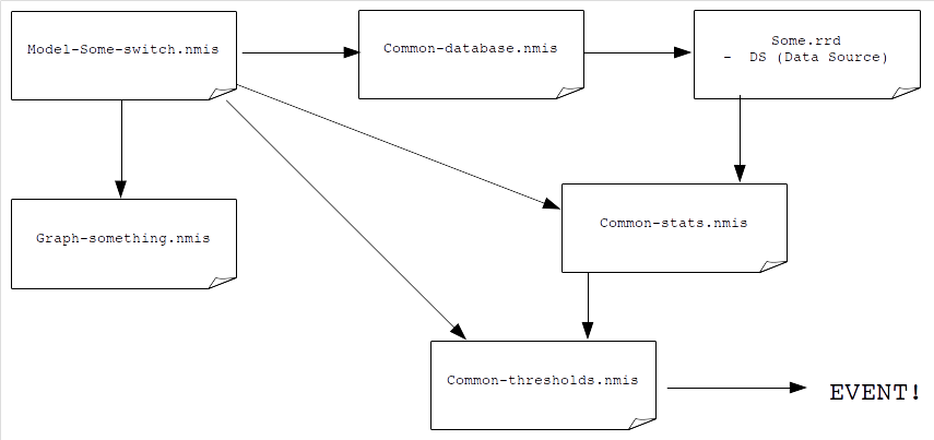
Relationship
Relationship of the files to each other, it may be useful to visualise how the files interact with each other.
Common Attributes
There are several common attributes that must match between these files in order for thresholding to work. In an attempt to demonstrate the relationship between these variables we'll use the following labels. Please reference the code block below for where they should reside.
...
echo - This variable is set in the Common-stats.nmis file. It is used to make computations on the zebra variable in the RRD language. This variable is then passed to the Common-threshold.nmis file in order to fire and event.
|
|
| |
|
|
Thresholds Controls
Simple Thresholds
In NMIS a simple threshold is defined by the following:
...
| Code Block | ||
|---|---|---|
| ||
'cpu' => {
  'item' => 'avgBusy5min',
  'event' => 'Proactive CPU',
  'select' => {
    'default' => {
      'value' => {
        'critical' => '70',
        'fatal' => '80',
        'minor' => '50',
        'warning' => '40',
        'major' => '60'
      }
    }
  }
}, |
Have a set of thresholds for Core CPU
However, Core devices are more sensitive to CPU Load. So we want to use a different set of threshold values. Something like:
...
But how to make these apply just to Core devices?
Advanced Thresholds with Controls
For example, different thresholds for core devices. Looking in Common-thresholds will give you some ideas, but you can add many “selects” and have properties like:
...
These are executed in the select order, and if no control is matched, then the default set is used.
Advanced Control Options
The following are the available control options:
...
- $hrStorageDescr
- $hrStorageType
- $hrStorageUnits (disk block size)
- $hrStorageSize (disk size in blocks)
- $hrStorageUsed (disk used in blocks)
- $hrDiskSize (disk size in bytes, hrStorageSize * hrStorageUnits)
- $hrDiskUsed (disk used in bytes, hrStorageUsed * hrStorageUnits)
- $hrDiskFree (disk free in bytes)
Sample Controls
The controls are little pieces of code which will be evaluated when needed, so you might want to do the following sorts of things.
Result | Control |
|---|---|
Use this threshold if the interface speed is between 1 and 5 megabits/second | $ifSpeed <= 50000 and $ifSpeed >= 10000 |
Use this threshold if the interface speed is 100 megabits | $ifSpeed == 100000000 |
Use this threshold if the interface speed is 10 megabits | $ifSpeed == 10000000 |
Use this threshold if the interface speed is 1 gigabits | $ifSpeed == 1000000000 |
Use this threshold if the disk is larger than 100 gigabytes | $hrDiskSize >= 104857600000 |
Apply the threshold to all devices starting with the IP address 192.168 | $host =~ /192\.168/ |
Apply the threshold to all devices in the group "Sales" | $group eq "Sales" |
Apply the threshold to all Cisco IOS devices | $sysDescr =~ /Cisco IOS/ |
Alerting
Basic Alerts
An alert is a custom event generated by testing the value of an OID or custom variable and producing a boolean result (true or false). If the test returns true, an event is raised and it will run through the escalation system, false will not raise an alert. Later on, when the test that was returning true once again returns false the event will be cleared.
...
test => this is a boolean operation using $r to determine if the alert should be raised
event => the name of the event when it is raised
level => the level of the event when it is raised
Test
This can be any Perl expression, and its evaluation result will be interpreted like perl does booleans (i.e. empty string, 0, undef means false, anything else means true).
...
A quick note on stringwise versy numerical comparison: in numeric mode, the expressions will be converted to numbers (i.e. string "0003" becomes the number 3 for comparison). In string mode the expressions' characters are compared one by one. If $r is "0003", $r == 3 is true, but $r eq 3 is false.
Where to add the Alert
The alert can be added to current variables being polled from the devices, or a new section can be added. For example a new section in Model->system->sys could be added which might look like the example below (the "--snip--" indicates that extra model code has been removed for clarity):
...
Adding the alert also adds the information to the "Device Details" panel, so you get the last polled value displayed all the time. Note that when you add such a basic alert its variable is collected independently of any other variables that your model might collect.
Example
The following is an example of the layout of an alert (in this example serialNum is taken from Model-CiscoRouter.nmis) and uses a string based (stringwise) comparison:
...
| Code Block | ||
|---|---|---|
| ||
'cipSecGlobalActiveTunnels' => {
  'oid' => 'cipSecGlobalActiveTunnels',
  'title' => 'Global Active Tunnels',
  'alert' => {
    'test' => '$r == 0',
    'event' => 'No tunnels present',
    'level' => 'Critical'
  }
} |
More Advanced Alerts
Alerts can also be created in the 'alerts' section of the model. lets created in this section have the advantage of being able to use values from a whole section of data to determine if the alert should be triggered or not; however, such alerts can NOT access variables collected/modelled in the 'system' section and as such are mostly useful for systemHealth modelling.
...
- 'services' defines what section the values being used for the alert are taken from. In this case services won't be found in the model because it is a special section just for servers. Normally you will not need to worry about special sections. Please note that you CANNOT use the 'system' section for advanced alerts!
- 'HighProcessMemoryUsage': this creates a label/id for the alert
- 'type' => 'test': this means the alert will test a single condition. The options are ['test', 'threshold-rising', 'threshold-falling']
- 'test' => 'CVAR1=hrSWRunPerfMem;$CVAR1 > 300000' defines a custom variable and then uses that variable to perform a boolean test.
- See the paragraph below regarding custom variables.
- 'value' => 'CVAR1=hrSWRunPerfMem;$CVAR1 * 1': this defines how the value that triggered the alert should be reported and displayed when the alert is shown in the GUI
- 'unit' => 'KBytes': the unit that the above value will be displayed with
- 'element' => 'hrSWRunName': which OID/value that has the problem, a descriptor or identifier. In this case it is showing the name of the process that has high memory usage.
- 'event' => 'High Process Memory Usage': sets the name of the alert event
- 'level' => 'Warning': the level the event will be triggered with. When using thresholding this is not used as the thresholds define the level.
Custom Variables
Please note that in NMIS versions before 8.6 you can only use one custom variable in a test expression, namely CVAR. This limitation has been removed in NMIS 8.6, and the limitation also never applied to value or control expressions.
...
CVAR2=ifAlias; "$CVAR2" =~ /some description/
Thresholding VS Alerting
When to use
Running a Model
Debugging Device Modelling
Advanced Modelling Options
Regex OID
Control
Calculate
ParseString
Replace
The result of the collection can be replaced by a given value from a predefined lookup table. In this case the value 1 or 0 will be replaced by the string "yes" or "no".
...
'0' => 'no'
}
No graphs
If we do not have the need to display a graph as part of a table of the systemHealth section, the option 'graphtype' must be replaced by: 'no_graphs' => '1'
Not saving to RRD (nosave)
If data is collect using snmp by the model to be displayed but there is no need to save it to RRD, the option "nosave" should be used.
...
Please note that setting nosave disables alerts for the given object.
index_regex
Used in the "SystemHealth" section, allows multi-element indexing: normally SNMP tables are indexed by the last, single numeric OID component. When NMIS does an update on a indexed entity, it iterates through all the known values for this index component and records them. This iteration does not work if the index consists of more than one number, as it does on certain equipment. In such cases you can set index_regex to a value that captures the OID components that vary between table elements. For example,
...
ensures that the last three numbers are used for indexing.
Additional Options
calculate
Format: expression
...
The result of evaluated expression replaces the originally collected value.
Advanced Modelling: Custom variables
Occasionally you will come across a device or a situation where collecting a single SNMP variable is insufficient, for example when two or more SNMP properties need to be combined to provide a meaningful measurement.
NMIS version 8.4.8G and later support modelling such scenarios using custom variables, or CVARs. With this mechanism you can temporarily capture up to 10 separate SNMP properties as a CVAR and define an arbitrarily complex expression (in perl) that transforms these CVARs into the one measurement that you want to collect and/or display.
Where and How to use CVARs
CVARs are supported
- in the
testandvalueexpressions in the NMIS alert and threshold subsystem, - in
calculateexpressions in the general modelling subsystem, - and from NMIS version 8.6 on, also in
controlexpressions evereywhere (in versions before that only a singleCVARwas supported incontrol).
To use CVARs you define the required CVARs as holding a previously specified SNMP variable at the beginning of one of the supported expressions; Subsequently you can then reference the CVAR value in the part of the expression that calculates the desired value to be used by NMIS.
An example scenario
The DS3 MIB defines a variety or error counters for DS3 circuits like "dsx3CurrentLCVs" which are based on a 15 minute observation interval and reset automatically at the end of the interval. As the interval start and end is arbitrary and up to the device to set, just capturing the error counters themselves is not quite workable. However, the DS3 MIB also specifies the variable "dsx3TimeElapsed" that holds the seconds elapsed since the start of the current observation interval. Dividing the raw error counter by the number of seconds into the interval results in a normalised errors-per-second rate which works well for collection and display.
Here is an excerpt of the relevant model file:
| Code Block | ||
|---|---|---|
| ||
'systemHealth' =>
{
    'sections' => 'ds3Errors',
    'sys' =>
    {
        'ds3Errors' =>
        {
            'indexed' => 'dsx3CurrentIndex',
            'index_oid' => '1.3.6.1.2.1.10.30.6.1.1',
            'headers' => 'ds3intf,ds3linestatus',
            'snmp' => {
                'ds3intf' => {
                    'oid' => '1.3.6.1.2.1.2.2.1.2', # ifDescr
                    'title' => 'DS3 Interface',
                },
                'ds3linestatus' => {
                    'oid' => '1.3.6.1.2.1.10.30.5.1.10', # dsx3LineStatus
                    'title' => "DS3 Line Status",
                    'calculate' => 'my @x; my %triggers=(1,"No Alarm",2,"Rx Remote Alarm",4,"Tx Remote Alarm",8,"Rx AIS",16,"Tx AIS",32,"Rx LOF",64,"Rx LOS",128,"Loopback",256,"Test Pattern",512,"Unknown",1024,"Near end unavailable signal",2048,"Carrier Equip OOS"); while (my ($num,$txt)=each(%triggers)) { push (@x,$txt) if (int($r) & int($num)); }; return join(", ",@x); ',
                },
...
                'ds3LCV' => {
                    'oid' => '1.3.6.1.2.1.10.30.6.1.6', # dsx3CurrentLCVs
                    'title' => 'Line Coding Violations per second',
                    'calculate' => 'CVAR1=ds3Elapsed; return ($CVAR1? $r/$CVAR1 : 0);',
        },
    },  # sys

    'rrd' => {
        'ds3Errors' => {
            'indexed' => 'true',
            "graphtype" => "ds3Errors",
            "snmp" => {
                'ds3Elapsed' => {
                    'oid' => '1.3.6.1.2.1.10.30.5.1.3', # dsx3TimeElapsed
                    'title' => 'elapsed seconds in current measurement interval',
                    'option' => 'gauge,0:U',
                },
...
                "ds3LCV" => {
                    'oid' => '1.3.6.1.2.1.10.30.6.1.6',
                    'option' => 'gauge,0:U',
                    'title' => "Line Coding Violations per second",
                    'calculate' => 'CVAR1=ds3Elapsed; return ($CVAR1? $r/$CVAR1 : 0);',
                },
    },  # rrd
}, # systemhealth |
In the example above, the calculate expressions are used in two ways:
- to transform the bitfield variable "DS3 Line Status" into a more verbose textual list of component statuses,
- and to divide the raw
dsx3CurrentLCVserror count by thedsx3TimeElapsedinterval length.
In both cases the syntax is very straight-forward:
- The expression must be a valid perl statement and return exactly one value.
- The tokens
$r, andCVAR0toCVAR9are interpreted by NMIS; everything else is perl. - Defining and using local variables with
myis ok, but don't attempt to change any global NMIS variables. "CVAR1=some_snmp_var;" defines what SNMP object CVAR1 is supposed to hold. The parser understandsCVAR0toCVAR9for a total of 10 captures.- You can use functions that were defined elsewhere in NMIS in your
calculateexpression.
You will likely have to include the full module namespace in the function call, e.g.func::beautify_physaddress(...).
Only functions without side-effects should be used. - "
return $r/$CVAR1;" accesses the value ofCVAR1in an expression. The variable "$r" represents the SNMP variable that thecalculateexpression is attached to.
Please note that
- the
$CVARn replacement in the expression is performed on a purely textual basis, before the expression is handed to the perl interpreter for evaluation :For string variables you have to provide quotes in your expression, e.g.
| Code Block | ||
|---|---|---|
| ||
calculate => 'CVAR1=somestringthing; return 42 if ("$CVAR1" eq "online");' |
- Numeric variables can be used straight without quotes.
- the
$CVARn access refers to the raw value of the named property, ie. the data before anyreplaceorcalculateexpressions for the named property were evaluated.
How to keep temporary CVAR data out of the RRD databases
As outlined above all the objects that you want to access via CVARs must be defined in the same section. If your test/calculate expression is within an rrd section, all the other objects will have to be within that rrd section, too, and thus they would be collected by NMIS and stored in RRD - quite wasteful if these other variables are just temporary and only there to for access using one CVAR expression.
In versions 8.6.0 and above you can prevent this by adding an option with value nosave:
| Code Block | ||
|---|---|---|
| ||
'snmp' => {
  'hrNumUsers' => {
     'oid' => 'hrSystemNumUsers',
     'option' => 'nosave',
}, |
In the example above, hrNumUsers would be retrieved with SNMP, and other variables could be defined in terms of e.g. CVAR3=hrNumUsers, but hrNumUsers would not be saved.
Please note that setting nosave disables alerts for the given object
Plugins
NMIS8 Plugin Operation
NMIS8 Plugins will run for any node which is active, but logically a plugin needs to be able to know what type of node it is operating on. Plugins will generally include early in the code a statement to look for a specific model type and if the model is of a type interesting to it, it will perform its duties, otherwise it will skip (return nothing).
To have an API Only node, the best method is to set active to true, and ping, collect, collect_snmp and collect_wmi to false and manually change the model from "automatic" to be the name of the model which will be used by the plugin. Because there is no data provided by the device we do not know how to automatically discover how to talk to the device, NMIS needs a little nudge to know how to talk to the device. You can see an example of this with the CiscoMerakiCloud and CiscoViptelaCloud models and plugins, which work with Cisco Meraki and Cisco SDN WAN (Viptela) respectively.
Intro (Concepts)
Basic Plugins
Examples
******* Use CMD8TEMP plugin as example ( https://support.opmantek.com/browse/SUPPORT-6061)
NMIS8 Node Polling Configuration
NMIS versions up to and including NMIS 8.6.7G
The following indicates how NMIS will behave when provided with various configuration options, this is specifically concerned with active, ping and collect.
Polling Description | active | ping | collect | plugins | services |
|---|---|---|---|---|---|
Regular node polling, the node will be ICMP polled and will have SNMP and WMI (if credentials configured) data collected | true | true | true | Will be run | will be polled if configured |
SNMP Only Node, the not will have SNMP collected but ICMP polling will not be performed. | true | false | true | Will be run | will be polled if configured |
Ping Only Node, the node will only be polled using ICMP. | true | true | false | Will be run | will be polled if configured |
Service Only Node, the node will only have services collected if they are configured. | true | false | false | Will be run | will be polled if configured |
Node is NOT active and NMIS will mostly ignore the node. | false | N/A | N/A | N/A | N/A |
NMIS versions after and including NMIS 8.6.8G
The following indicates how NMIS will behave when provided with various configuration options, this is specifically concerned with active, ping and collect.
Polling Description | active | ping | collect | collect_snmp | collect_wmi | services |
|---|---|---|---|---|---|---|
Regular node polling, the node will be ICMP polled and will have SNMP and WMI (if credentials configured) data collected | true | true | true | true | true | will be polled if configured |
SNMP or WMI Only Node, the not will have SNMP collected but ICMP polling will not be performed. | true | false | true | true | true | will be polled if configured |
Ping Only Node, the node will only be polled using ICMP. | true | true | false | false | false | will be polled if configured |
Service Only Node, the node will only have services collected if they are configured. | true | false | false | false | false | will be polled if configured |
API Only Node, the node will use plugins to collect data, no other polling will be done, except services if configured. | true | false | false | false | false | will be polled if configured |
Node is NOT active and NMIS will mostly ignore the node. | false | N/A | N/A | N/A | N/A | N/A |
Model Policy
NMIS 8.6 introduced a new mechanism for adjusting a model's behaviour for particular nodes: the Model Policy system. In version 8.6.0G it allows you to specify flexible rules for adding or removing systemHealth model sections for specific nodes (or groups of nodes).
The Model Policy Document
The installer will install a default model policy document in conf/Model-Policy.nmis. The original/default file will also remain available in the install directory, and contains helpful comments.
...
It should be noted that as Only the first matching rule is applied and therefor the default rule is not subsequently applied you should include all the relevant "false" sections from the default rules into your rule. For example if you wanted to turn on just one mpls system health section you would set that as true in your rule and you would also include all the other "false" lines which are relevant to your model in the rule.
Example Policy
Here is a partial example policy:
...